Load tests on piles are conducted on completion of 28 days after casting of piles. Two types of tests namely initial and routine tests, for each type of loading viz. vertical, horizontal (lateral) and pull out, are performed on piles.
Initial Load Tests on Piles
This test is performed to confirm the design load calculations and to provide guidelines for setting up the limits of acceptance for routine tests. It also gives an idea of the suitability of the piling system. Initial Test on piles are to be carried out at one or more locations depending on the number of piles required. Load applied for the initial (cyclic) load test is 2.5 times the safe carrying capacity of the pile. Loading for Initial Tests is conducted as per Appendix ‘A’ Clause 6.3 of IS-2911 Part IV.
Routine Load Tests on Piles
Selection of piles for the Routine Test is done based on number of piles required subject to maximum of ½% of total number of piles required. The number of tests may be increased to 2% depending on the nature / type of structure. The test load applied is 1½ times the safe carrying capacity of the pile. The Maintained load method as described in Clause 6.2 of IS-2911 (Part IV) – 1985 shall be followed for loading for the Routine Tests.
This test will be performed for the following purposes:
1- To ensure the safe load capacity of piles
2- Detection of any unusual performance contrary to the findings of the Initial Test.
The tests shall be performed at the cut-off level only. A detailed report for the test result is prepared.
1- Vertical Load Tests on Piles
This test will be carried out as stipulated in IS-2911 (Part IV) 1995.
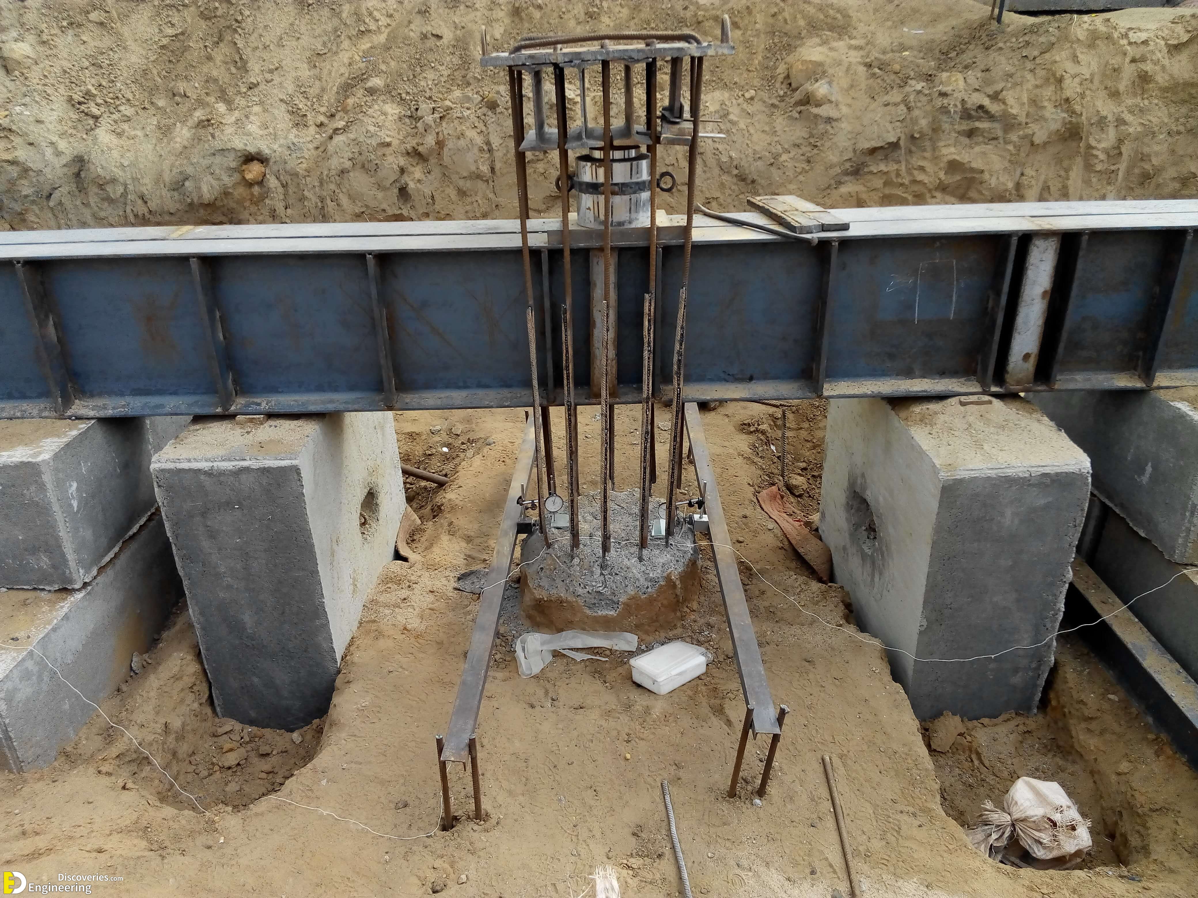
Pile Head: The pile head shall be chipped off till sound concrete is met wherever applicable. The reinforcement shall be cut and head levelled with Plaster of Paris. A bearing plate with a hole shall be placed on the head for the jack to rest.
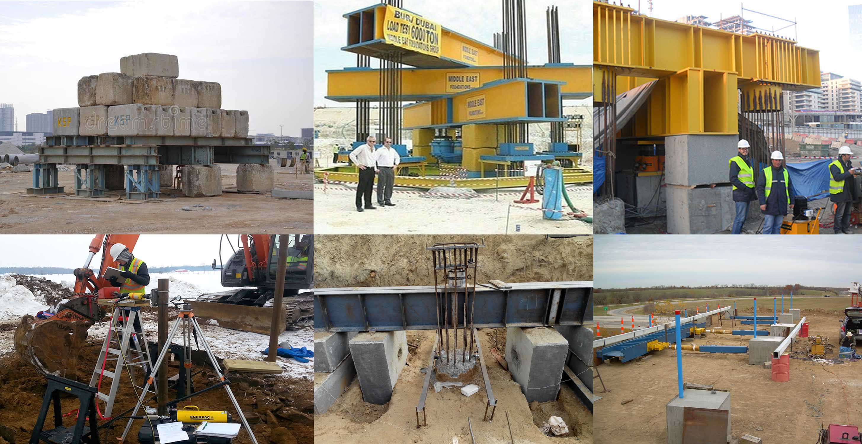
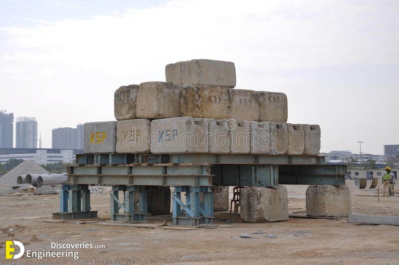
Reaction: Kentledge shall be suitably designed to get the desired reaction on the piles. Anchor piles (if required) shall be placed at a center to center distance of 3 times the pile diameter subject to a minimum distance of 2 M.
Settlement: 2 dial gauges for a single pile and 4 dial gauges for a group of piles with 0.01 mm sensitivity shall be used. They shall be positioned at equal distance around the piles on datum bars resting on immovable supports at a distance of 3D (min. of 1.5 m) where D is the diameter of pile or circumscribing circle for non-circular piles.
Application of load: It shall be applied as specified depending on the type of test (routine / initial). Each load shall be maintained till the rate of displacement of the pile top is either 0.1 mm in the first 30 minutes or 0.2 mm in the first one hour or 2 hours whichever occurs first. The next increment in the load shall be applied on achieving the aforesaid criterion. The test load shall be maintained for 24 hours.
Initial Tests: The safe load on a single pile shall be the least of the following:
1- 2/3rd of the final load at which the total displacement attains a value of 12 mm unless otherwise required in a given case on the basis of nature and type of structure in which case, the safe load should be corresponding to the stated total displacement permissible.
2- 50% of the final load at which the total displacement equals 10% of the pile diameter in case of uniform diameter piles or 7.5% of the bulb diameter in case of under reamed piles.
2- Lateral (Horizontal) Load Tests on Piles

The jack should be placed horizontally, between two piles. The load on the jack shall be the same on both the piles. The load will be applied in increments of 20% of the estimated safe load and at the cut off level. The load will be increased after the rate of displacement is nearer to 0.1 mm per 30 minutes. If the cut-off level is approachable, one dial gauge exactly at the cut-off level shall measure the displacement. In case the cut-off level is not approachable, 2 dial gauges 30 cm apart vertically, shall be set up and the lateral displacement of the cut-off level calculated by similar triangles.
The safe load on the pile shall be the least of the following:
a) 50% of the final load at which the total displacement increases to 12 mm.
b) Final load at which the total displacement corresponds to 5 mm.
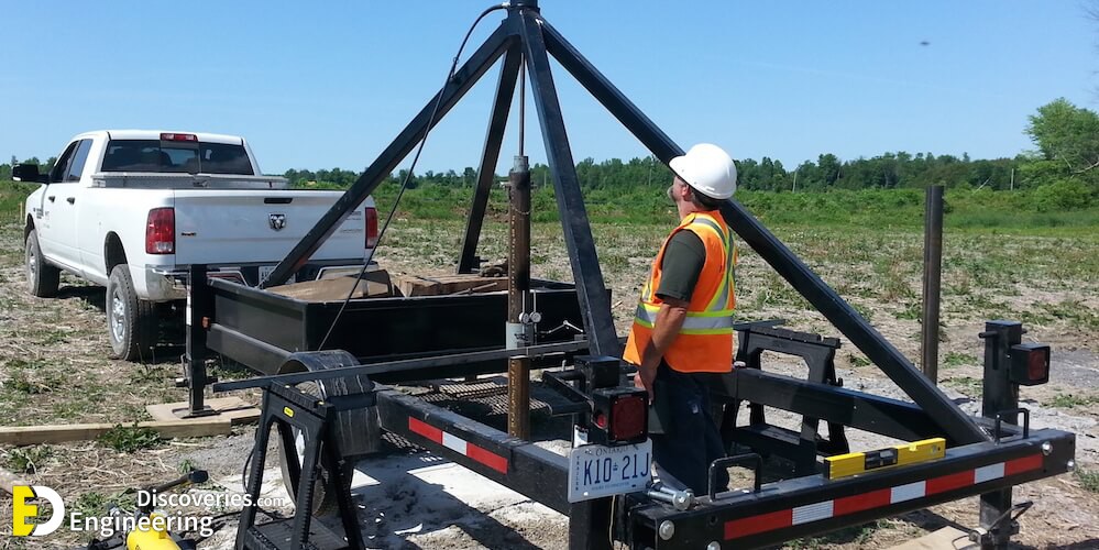
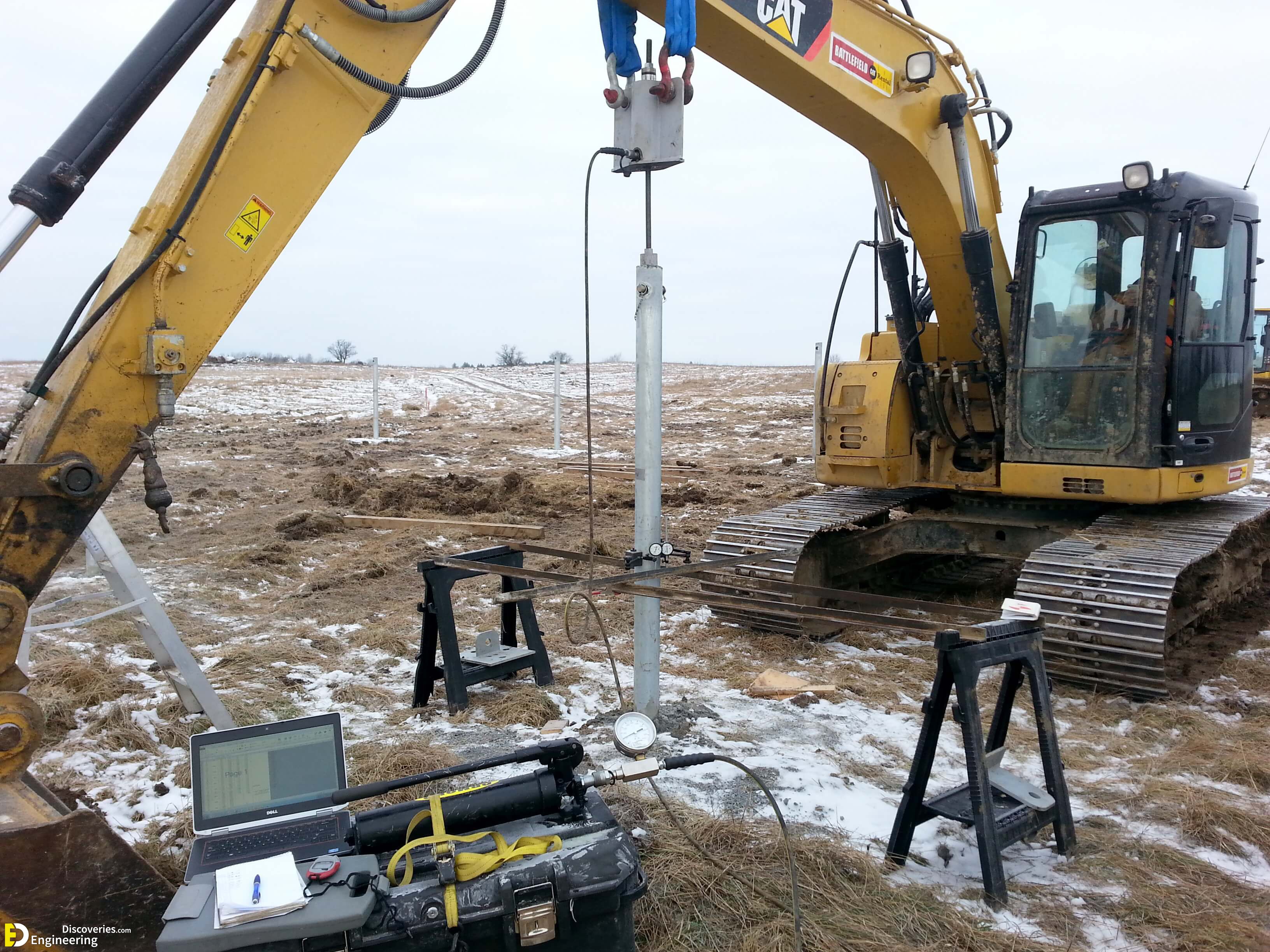
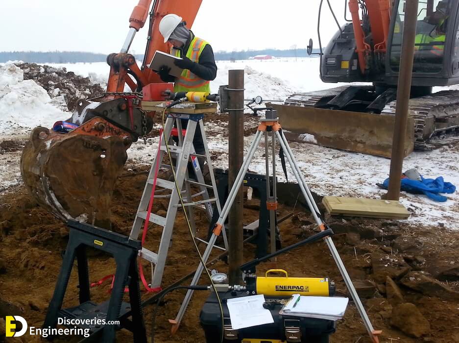
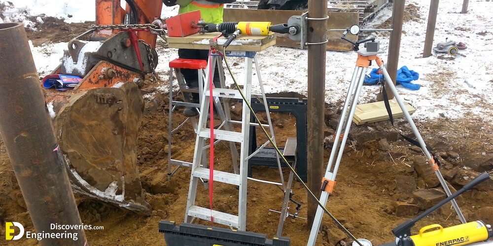
3- Pull out Tests on Piles
Specified by ASTM standard D3689, axial uplift pile load tests ( pull out tests) have become the most common pile load tests in the solar industry. By applying a vertical tensile load and simultaneously measuring pile displacement, engineers can determine the minimum overall embedment that’s required to account for design loading. Additionally, this test is often used by contractors and developers during pile installation as a means of verifying successful pile installation. If your project needs axial uplift pile load tests (pull out tests)